Ras Pi Gardener
I’m not exactly sure why it is, but it seems like there’s a lot of people on the internet building, shall we say, “gardening assistive devices” aka taking their raspberry pis and using them to monitor soil moisture. I think it’s because this sort of project sits right at the overlap of coding, electronics, and real-world utility. Either way, I spent quite a lot of time doing research and implemented a prototype. There are a lot of different ways to implement it but in general you measure an electrical signal and interpret it as a proxy for soil water content, and then alert or log as you wish.
Building a transducer
There are all sorts of ways to interpret soil moisture as an actionable electrical signal but the two common ones are using electrodes and measuring resistance or measuring capacitance. Resistance causes electrolysis on one of the electrodes and possibly also messes with your soil pH so I opted for a capacitive sensor. Lots of designs online had fancy 555 timers and RC oscillators but after fiddling around with breadboards and my oscilloscope I opted for a simpler design.
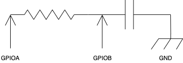
The theory is that you pull GPIO A high, which will charge the capacitor (your capacitive moisture probe) across the resistor (I used 47 kOhm because that’s what I happened to have lying around) and then measure how long it takes for the voltage at GPIO B to flip to High, which in CMOS logic is around 2 Volts. Then you pull GPIO A low again to discharge the capacitor. Repeat as often as you like to average the results together.
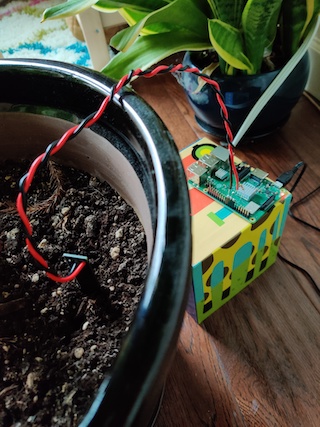
I have a nice collection of Raspberry Pis, Beaglebone Blacks, and STM32 Black Pills kicking around. Using the GPIO pins and a resistor it’s fairly simple to set up a proxy measurement using a capacitive probe. The probe itself is a simple PCB with interleaving traces that form the planes of a capacitor. It gets inserted into the soil and connected to the microcontroller or RasPi with two wires. The probe is a design I found on github somewhere and had fabricated at PCBway. I’ve long since lost the link to the original repository so I’ve included the CAD files in my git repo in case anyone wants to try their own hand at it.
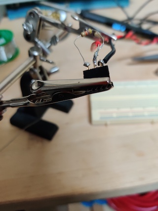
After getting the PCBs fabbed it’s a simple matter of soldering a pair of wires to it and then doing the same with some female pin headers. Add a resistor across the charge terminal of the capacitor and the other GPIO pin and you’re set.
Interpreting the signal
I used a Raspberry Pi Model 3B+ because that’s what happened to be lying around, but there’s no reason you couldn’t do this on anything with sufficient speed and some GPIO pins. Because it’s a Ras Pi, I opted for Python 3, which is the lingua franca of the Raspberry Pi world. I wanted to use Common Lisp but the only GPIO libraries I could find didn’t seem to produce any effect/were nonfunctional.
I thus leaned heavily on two libraries: RPi.GPIO and IRC. More on the IRC library later. First we set up “Broadcom Numbering” which is to say we address the pins logically rather than by their physical positions on the board header, and then we set Pin 23 as the charge/discharge pin (an output) and Pin 24 as the pin where we’ll take our voltage measurements (an input). Then we’ll add an event to listen for Rising edges on pin 24:
chargePin = 23
measurementPin = 24
...
GPIO.setmode( GPIO.BCM )
GPIO.setup( chargePin, GPIO.OUT )
GPIO.setup( measurementPin, GPIO.IN )

GPIO.output( chargePin, GPIO.LOW )

GPIO.add_event_detect( measurementPin, GPIO.RISING )
A word to the wise: It looks like there’s a longstanding, unresolved bug with the add_event_detect function wherein spurious edges are “detected” and thus the callbacks that you set trigger erroneously. Further reading here.
In any case, once we’ve set up our event we can actually subscribe to it:
GPIO.add_event_callback( measurementPin, callback=lambda x: self.edge_callback() )
And then we are free to define a callback to do whatever we like when we encounter a rising edge on the input pin. In my case I opted for the following flow:
- Schedule a regularly-occurring function call that sets the charge pin high which will begin charging the capacitor
- The callback will automatically fire when we detect a rising edge on the input pin
- In the callback function’s body, set the pin low to discharge the capacitor and then do the timestamp arithmetic to determine how long it took to charge the capacitor.
- Decide, based on the computed value from the previous step, what to do.
It’s important to note that we don’t actually care what the capacitance value really is, so there’s no need to start solving for Tau constants and all that good stuff because physics dictates that the moisture content in the soil will alter the dielectric constant of our capacitive probe. So the charge/discharge time becomes a proxy measurement. We configure/calibrate the python script to look for charge times that correspond with “sufficiently wet” and “sufficiently dry” and act when the measured value exceeds those bounds.
Getting data off the microcontroller
I used a Ras Pi because, among all the random boards and low-power devices I had kicking around in my parts drawer, it has sufficient horsepower to run its own TCP/IP stack and the Model 3B+ in particular because it has onboard wireless networking. In a future iteration of this project I intend to run the detection code on an STM32 Black Pill which has no wifi module, meaning I will probably have to push the data out over I2C or other interface to get it into the network.
Once the data is on some kind of device that speaks TCP/IP however, we’re set. In this case I opted for the following setup:
- I run an instance of InspIRCd on a server that I control
- Each device such as my Raspberry Pi connects to IRC, which is a lightweight and simple protocol that’s easily implemented in a weekend (though I chose to use a library) and more importantly is easily debugged because it’s all just strings being sent over the network
- I run an instance of weechat inside a
tmuxsession on the same server as #1, andweechatruns a script called weebullet which allows me to receive push notifications on my phone via the Pushbullet service. To set this up it’s fairly simple, theweebulletreadme is enough. All you need is an API key from pushbullet:
- If any bot determines that I need to be alerted about something (say, my precious Norfolk Spruce is getting dry) then it highlights me in IRC and I get a push notification on my phone
Once that’s done it’s a simple matter of waiting until the soil gets dry enough, taking a snapshot of the capacitance measurement, and using that as our alerting threshold. Then give the tree or plant a good soaking and use that as the upper threshold.
Long-term persistence
There are two final things I needed to do in order to set this little project up for long-term success. The first is to install my python script as a system service so that it would come back up if the power went out:
[Unit]
Description=Raspberry Pi Gardener
After=systemd-networkd-wait-online.service
Requires=systemd-networkd-wait-online.service

[Service]
User=pi
WorkingDirectory=/home/pi
ExecStart=/usr/bin/python3 /home/pi/ircbot.py
Restart=always
RestartSec=10s

[Install]
WantedBy=multi-user.target
And the second was to enable the overlay file system on my ras pi so as to protect the SD card from excessive wear, which is a known design flaw with that series of boards. This used to be an enormous pain in the ass but in 2019 someone got sufficiently fed up and you can now easily toggle the read-only overlayfs from the raspi-config tool.
Full source code for my python script as well as the gerber files for the PCB probe are available on my github
Happy hacking!