Update: This post was featured on Hackaday!
DIY Door Detector Debugged
This is an update to/expanded version of a previous post about a DIY door sensor I built out of leftover stuff I had in my parts drawer. Cost: $0
Context
My house has a “basement”. I use quotes because the height of the ceiling down there is mostly six feet, but there are countless beams and ducts and plumbing and other protrusions such that only somebody about 5 feet six inches tall can actually walk down there, so it’s technically a crawlspace. Anyways, there’s a door to the exterior down there and my wife hates going down at night/alone to check if the deadbolt is locked, so with a spare beaglebone black I found lying in a drawer, I implemented a nice little sensor to tell us if the downstairs door is locked. Now I can check the lock status without getting out of my cozy bed!
GPIO Refresher
In general, it’s similar to the transducer I built for measuring soil moisture, where we take a resistor across the 3.3 VDC output and a GPIO pin. The switch (the door deadbolt) connects the GPIO pin to ground so that when the circuit is open there will be no voltage drop across the resistor, so the GPIO pin should read “high”. When the circuit is closed, current flows from the supply pin through the resistor to GND which will produce a voltage drop across the resistor and the GPIO pin should read “low”.
Then it’s a matter of building a transducer that will detect when the deadbolt is locked. Originally I wanted to use one of those small neodymium magnets paired with a Hall-effect or perhaps a magnetoresistive sensor to make the whole thing contactless and thus less prone to fatigue-related failures, but the clearance on the door is pretty tight. I would have had to drill a hole into the deadbolt to seat the magnet, and I decided instead to go lo-fi with it:
Super Duper Sophisticated Deadbolt Sensing Equipment
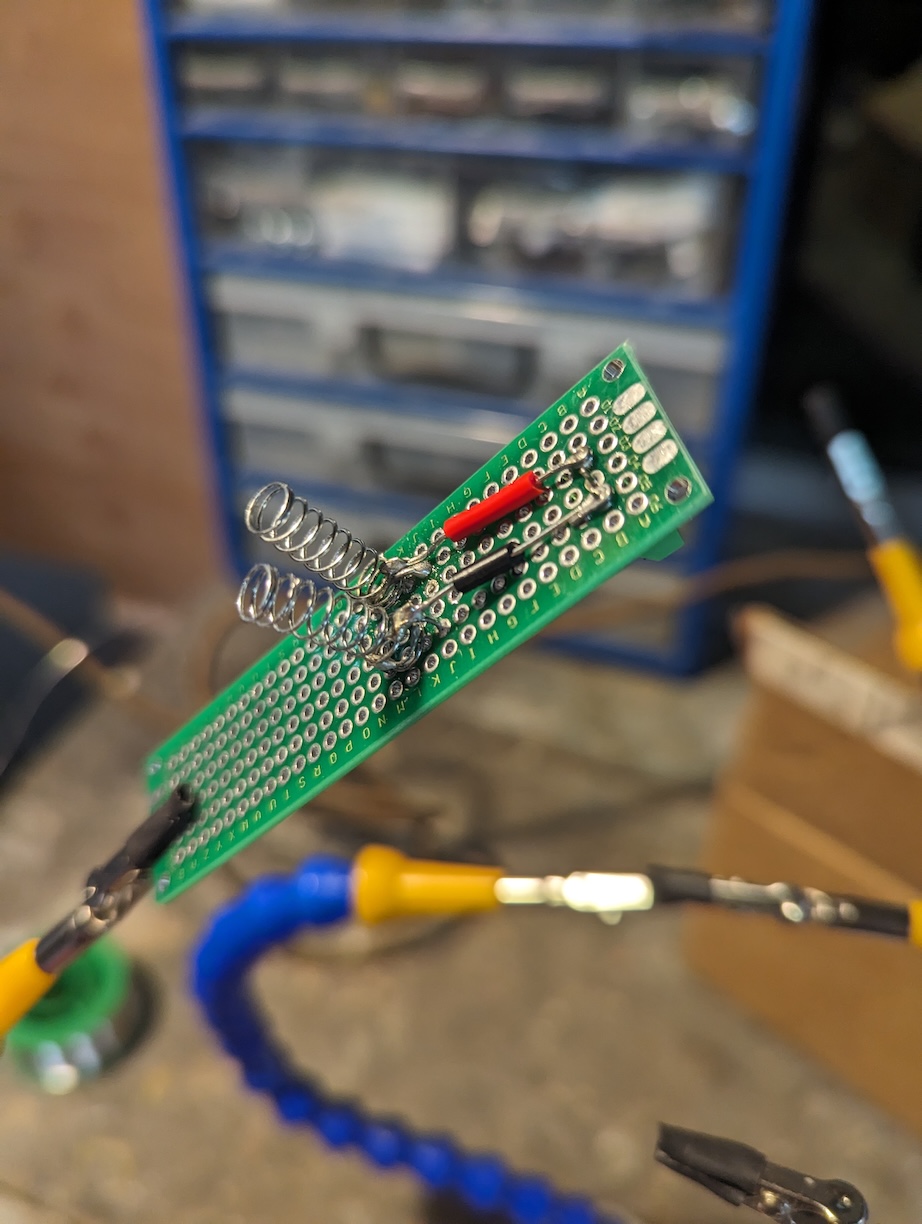
Instead of using electromagnetic sensors, I took two springs out of ballpoint pens and soldered them to some perfboard I had lying around.
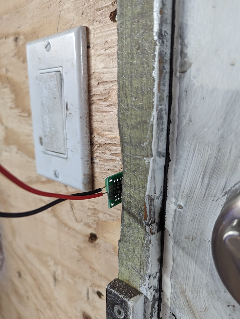
After that I drilled a hole into the wall so that I could access the cross bore (which is the hole where the deadbolt engages the frame when locked) and used a keyhole saw to cut slots in the shape of the perfboard. Then I simply squeezed the spring contraption in so that the deadbolt contacts the two springs when locked, causing them to buckle and completing the circuit.
After that, the remainder of the hardware was a not-so simple matter of running about 16 feet of wires up and around the corner, making a small terminal board for the other end of the wires, and then connecting it to GPIO. My initial attempt (discussed in a previous post) was suffering from spurious event detection, and I didn’t have time to debug it until recently.
Noise
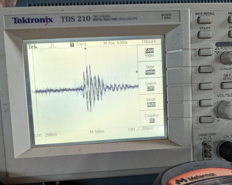
As I said, the run of wires from the BBB to the door frame is about 16 feet. I used a drill to twist the wires together, Ethernet-style, hoping to keep the noise pickup down. I got out my battered but trusty old oscilloscope to measure. The twists helped, but not as much as I hoped they would. There was what looked like HF “ringing”, maybe from the spring contacts closing or maybe just some kind of weird transient in the circuit. You can see in this photo some kind of damped RF noise that lasts for a few microseconds, and from the scope settings (I don’t seem to have had the freq measuring feature enabled) it looks like 10-15 MHz or so. I am not an expert in the dark sorcery practised by electrical engineers, so take the interpretation of these two waveforms with a grain of salt.
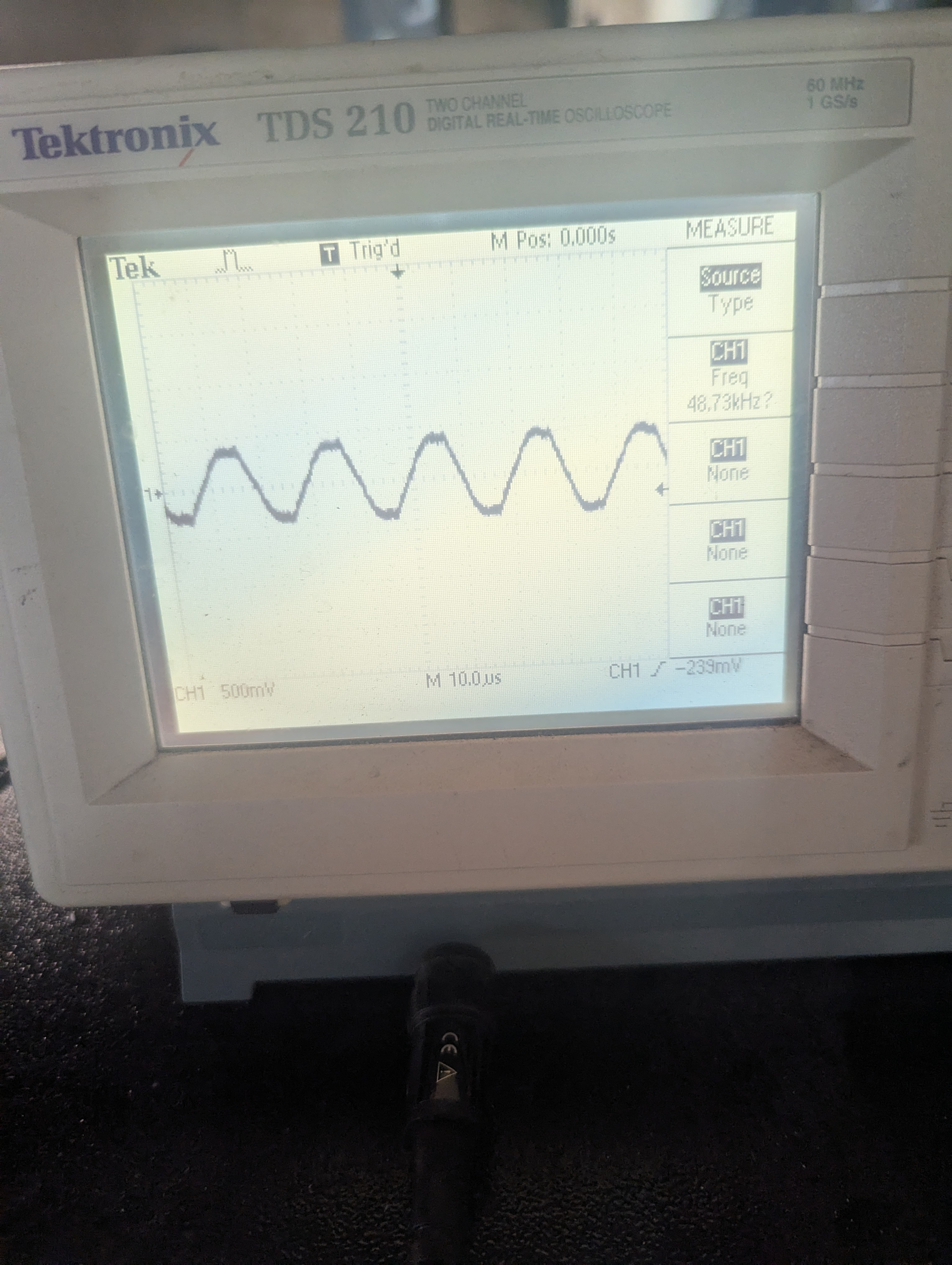
There was also a pretty prominent signal at around 48kHz to contend with, which I think is probably from the switching power supply inside the fluorescent fixture less than a foot away.
In any case, the twisted nature of the wiring did help somewhat, but not as much as just adding an RC low-pass filter.
Capacitors to the rescue
I had to dig out my electronics textbook from undergrad for this, but there are two primary considerations:
- The capacitor’s
tauor RC constant represents the time to charge to about 63.5% of full voltage, and we’re on 3V3 here since the BBB is not 5V-tolerant on its IO. If we set an RC constant too high, it will take longer for the voltage level to rise high enough to trigger a logical High on the BBB. - The RC filter’s cutoff frequency needs to be low enough to attenuate 60Hz mains noise and whatever else we’re picking up.
I managed to find a 10uF capacitor in my parts drawer, and with a 2.2kOhm resistor that makes for a capacitor tau of about 22ms. The lowest voltage level on the BBB that corresponds to a logical High is 2.0V per the AM335x datasheet, which is less than 63% of 3.3V, meaning the time between the circuit closing and the rising edge being detected is going to be less than 22ms, which is plenty fast.
Additionally, the cutoff frequency fc = 1 / (2 * pi * R * C) comes out to about 7Hz, which is plenty low.
One more hardware change
Some kind people on reddit pointed out that most designs aim to avoid having to “long haul” Vcc out to the switch and back. Rather, it’s better to put the switch between GPIO and GND, and have a pullup resistor across Vcc and GPIO. I built a new terminal board, and the final circuit came out looking like this:
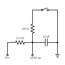
It was also suggested to me to put a very small resistor in series with the switch for ESD protection, and I happened to find a 100 Ohm resistor in my drawer, so in it went. All in all it works great.
Software debounce
The 10uF capacitor basically eliminated all the noise, but I still did occasionally get some spurious duplicate events being detected when I closed or opened the deadbolt. I suspect this is due to the springs being a very “noisy” way to complete a circuit, and they’re probably clanging away against each other in there. Thankfully, Adafruit’s BBIO library has a handy dandy built-in feature for debouncing: link to docs
So it was a simple matter of specifying that bouncetime value in my code:
GPIO.add_event_detect(config.pin, GPIO.BOTH, callback=self._gpio_callback, bouncetime=config.bounce_ms)
With all that done, I finally get crisp single events every time the deadbolt is actuated!
Super Duper Sophisticated Telemetry Protocol
I am a perennial skeptic of cloud-enabled IoT devices. Instead of using some kind of IoT dashboard I just run an internal IRC network. Since it’s such a simple and well-established protocol there are libraries for it in almost every language, and it’s really easy to get low-power devices onto it so long as they can speak TCP/IP, which the BBB can.
So I’ve integrated the BBIO logic with an IRC bot that sits in a channel along with my Raspberry Pis that tell me when my plants need water, and my algorithmic trader bot that tells me when a position gets opened or closed.
Doorbot is on GitHub and dutifully waits until the deadbolt changes state, and then calmly announces it to the channel. Could I simplify this setup? Certainly, but it would be less fun.